Welcome to BKPOWER!

UPS Power Factor and Load Power Relationship: Selection Guide
TIPS:In the realm of power management, the relationship between UPS power factor and UPS maximum load power is a crucial aspect. Power factor, a key metric, directly influences how effectively a UPS can handle its maximum load. This article delves into the definitions of UPS power factor and UPS maximum load power, exploring their intricate connection. Discover how load equipment power factor impacts this relationship, and learn practical insights into UPS selection based on different power factor scenarios. Uncover how our advanced voltage stabilizer solutions can optimize this dynamic, ensuring reliable power support for diverse industries, whether you’re considering a portable power station, uninterruptible power supply, or other related power equipment.

Ⅰ. Abstract
In the complex landscape of power management, understanding the relationship between UPS power factor and UPS maximum load power is essential. Power factor, a key metric, deeply influences both the performance of Voltage Stabilizer and the operational capacity of UPS systems. This article precisely defines UPS power factor, UPS maximum load power, and load equipment power factor, unraveling their intricate interconnections. Explore how varying load power factors impact UPS selection and discover practical examples of optimal selection. Learn how our advanced Voltage Stabilizer products optimize this relationship to deliver efficient, reliable power solutions across industries.
Ⅱ. Detailed Analysis of the Relationship Between UPS Power Factor and Maximum Load Power
1. Definition of UPS Power Factor
UPS Power Factor is a critical indicator of electrical efficiency, defined as the ratio of active power (actual work – producing power) to apparent power (total power from the UPS). Formula: Power Factor = Active Power / Apparent Power.
- Active Power (W): The power consumed by loads for useful work (e.g., motor operation, lighting).
- Apparent Power (VA): The total power supplied by the UPS, including reactive power (energy exchanged with inductors/capacitors without doing work). A PF of 1 means full efficiency (current and voltage in phase). In reality, PF < 1 due to load characteristics, leading to reactive power losses.
2. Definition of UPS Maximum Load Power
UPS Maximum Load Power refers to the maximum power a UPS can safely drive under normal operation, stated in VA or W. Key constraints include:
- Internal Hardware: Inverter capacity (limits power conversion), battery discharge capability, and circuit board load tolerance.
- Heat Dissipation: Inadequate cooling causes UPS to derate, reducing maximum load.
- Battery Capacity: Determines sustained power during outages; insufficient capacity limits load duration.
3. Definition of Load Equipment Power Factor
Load equipment power factor measures how efficiently a load uses electrical energy, also defined as the ratio of active to apparent power. It varies widely by load type, directly impacting UPS selection and operation.
4. Interrelationships Among the Three
- UPS PF & Maximum Load: UPS ratings are in VA, but actual active power output depends on PF. Example: A 10kVA UPS with PF 0.8 delivers 8kW. Mismatched load PF can overload the UPS even if VA rating is unexceeded.
- Load Equipment PF Impact: Low PF loads require more reactive power, increasing UPS current, losses, and heat—reducing effective maximum load. High PF loads optimize UPS capacity utilization.
- Synergistic Effect: UPS PF defines output capability, maximum load sets power limits, and load PF influences operational state. Matching all three ensures system stability.
5. Impact of Different Load PF on UPS Selection
- Low PF Loads (0.5–0.8): Inductive devices (motors, transformers). Require oversized UPS with 30%+ margin to avoid overload. Pair with PFC or Voltage Stabilizer for improved efficiency.
- High PF Loads (≈1): Resistive loads (heaters, incandescent bulbs). UPS capacity can align closely with active power needs, promoting high efficiency.
- Non – linear Loads (0.6–0.8): Computers, switch-mode power supplies. Need UPS with harmonic suppression and wide PF adaptability, paired with Voltage Stabilizer for voltage stability.
6. Power Factor Classification of Common Load Equipment
| Load Category | Typical Devices | PF Range |
|---|---|---|
| Resistive | Electric ovens, incandescent bulbs | Close to 1 |
| Inductive | Motors, transformers | 0.5–0.8 |
| Capacitive | Some electronic power supplies | 0.8–0.95 (leading) |
| Non – linear | Computers, variable frequency drives | 0.6–0.8 |
7. Selection Examples
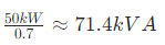
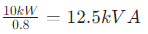
Case 1: Data Center
Loads: 50kW servers (PF 0.7), 10kW network equipment (PF 0.8).
Calculations:
Server apparent power:
Network equipment apparent power:
Total apparent power:

Selection: 100kVA UPS (PF ≥0.9) with our high – precision Voltage Stabilizer to ensure reliability.
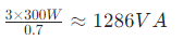
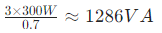
Case 2: Home Office
Loads: 3 computers (300W each, PF 0.7), 1 printer (200W, PF 0.8), LED lights (100W, PF 0.95).
Calculations:
Computer apparent power:
Printer apparent power:
Light apparent power:
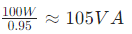
Total apparent power:

Selection: 2kVA UPS (PF ≥0.8) with our home – use Voltage Stabilizer for voltage protection.
Ⅲ. Conclusion
The relationship among UPS power factor, maximum load power, and load equipment power factor is critical for system efficiency and equipment selection. Understanding these dynamics enables precise UPS sizing. Our company offers scalable UPS solutions paired with high – performance Voltage Stabilizers, tailored for residential, commercial, and industrial needs—ensuring stable, efficient power supply.
References
- International Electrotechnical Commission (IEC)Official website: www.iec.ch
- Underwriters Laboratories (UL)Official website: www.ul.com
- European Committee for Standardization (CEN)Official website: www.cen.eu
- Standardization Administration of China (SAC)Official website: www.sac.gov.cn
- Zhongguancun Energy Storage Industry Technology Alliance (CNESA)Official website: www.cnESA.org
- International Organization for Standardization (ISO)Official website: www.iso.org