Welcome to BKPOWER!












Heavy Duty UPS Redundancy – N+1 Configuration
TIPS:A heavy duty UPS system with N+1 redundant UPS configuration represents the gold standard for critical power protection in modern industrial environments. This comprehensive guide explores how heavy duty UPS system architectures leverage N+1 redundant UPS topology to eliminate single points of failure and ensure seamless automatic failover. We examine parallel architecture principles, fault-tolerant switching logic, and practical implementation strategies for mission-critical applications including data centers, manufacturing facilities, and healthcare infrastructure.
Ⅰ. Introduction to N+1 Redundancy in Heavy Duty UPS Systems
Organizations operating critical infrastructure cannot tolerate power interruptions. A single UPS failure can cost millions in lost productivity and damaged reputation. N+1 redundancy solves this challenge.
N+1 configuration means deploying one more UPS unit than necessary to support your total load. If your facility requires 300 kVA, you install four 100 kVA units instead of three. When any single unit fails, the remaining three continue supplying full power without interruption.
This architecture differs fundamentally from N configuration (no redundancy) and 2N configuration (full duplication). N+1 strikes the optimal balance between reliability and cost. It provides fault tolerance without requiring 100% infrastructure duplication.
Heavy duty UPS systems implementing N+1 redundancy serve data centers, semiconductor manufacturing, medical imaging facilities, and telecommunications hubs. These environments demand continuous power availability measured in “nines”—99.999% uptime or better.
Ⅱ. Parallel Architecture Fundamentals
1. Load Sharing Principles Parallel UPS systems operate as a unified power source. Each unit shares the electrical load proportionally. In a four-unit N+1 system, each UPS carries 25% of the total load during normal operation.
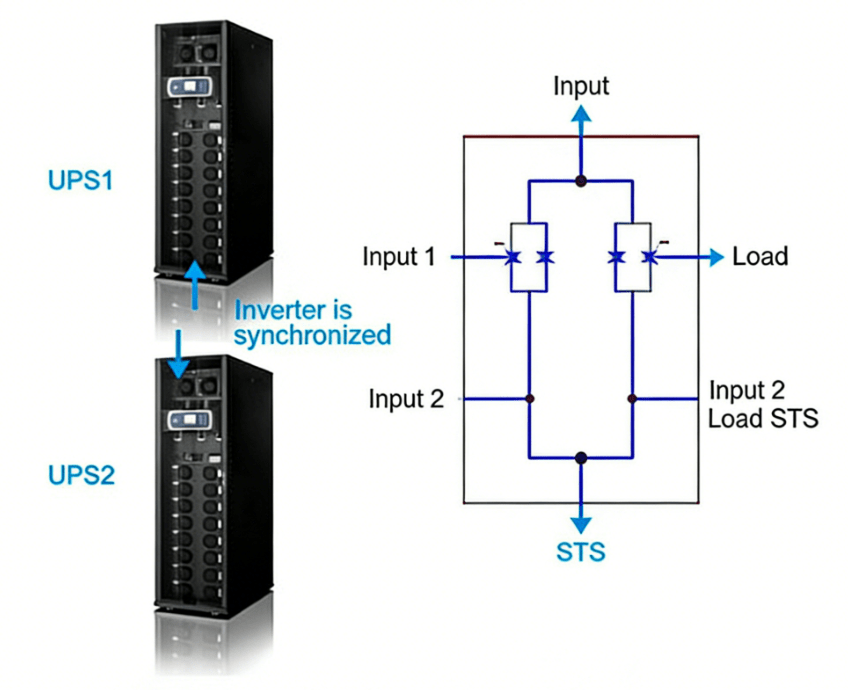
This load distribution requires precise synchronization. All units must maintain identical voltage, frequency, and phase angle. Modern digital signal processors (DSPs) control this synchronization within microseconds.
The parallel bus connects all UPS outputs. This copper busbar system enables current flow between units. High-speed communication links ensure real-time coordination.
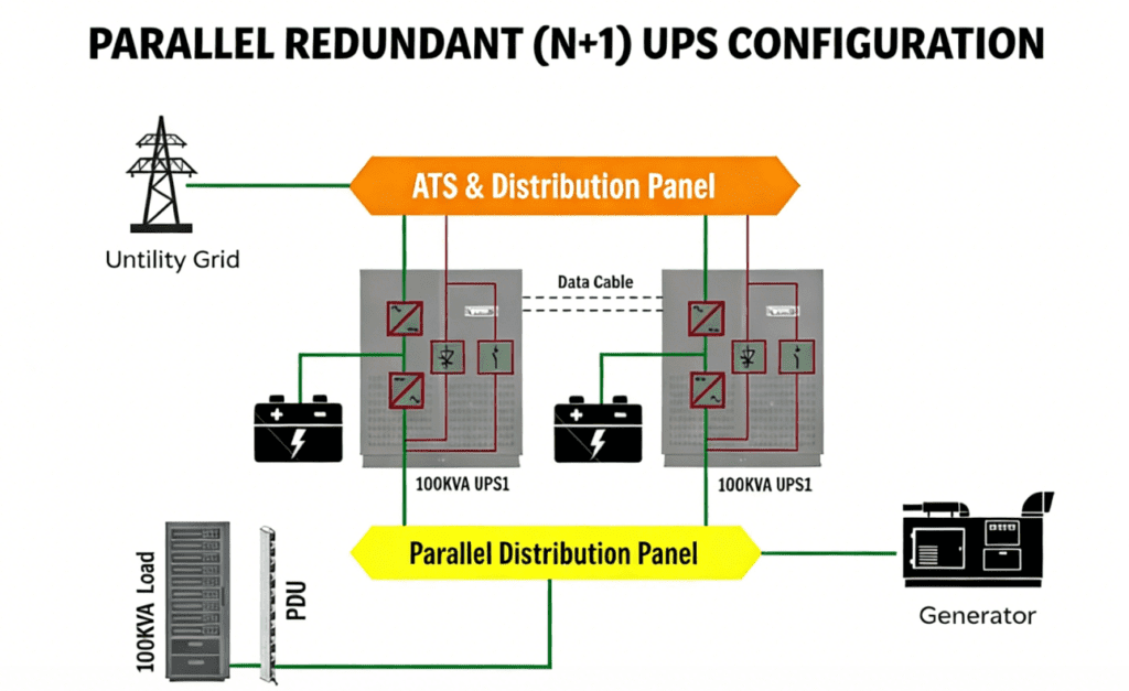
2. System Components An N+1 heavy duty UPS system includes:
- UPS Modules: Online double-conversion units rated for parallel operation
- Parallel Control Cabinet: Houses synchronization circuitry and load-sharing controllers
- Static Switchgear: Enables automatic transfer and isolation
- Battery Systems: Typically one battery string per UPS module for independence
- Maintenance Bypass: Allows individual unit servicing without system shutdown
3. Capacity Planning Proper sizing ensures N+1 redundancy works effectively. Each UPS must handle 100% of the load divided by (N). For a 400 kVA load with N+1 redundancy using 100 kVA units:
- Required capacity: 400 kVA
- Minimum units for load (N): 4
- Redundant unit (+1): 1
- Total installed: 5 units (500 kVA)
- Utilization per unit: 80%
This 80% loading provides headroom for temporary overloads and voltage sags.
Ⅲ. Automatic Failover Logic and Fault Tolerance
1. Failure Detection Mechanisms Heavy duty UPS systems monitor hundreds of parameters continuously. These include:
- Input voltage and frequency deviation
- DC bus voltage stability
- Inverter output waveform quality
- Internal component temperatures
- Battery health status
- Fan operation
When any parameter exceeds safe thresholds, the system classifies the condition. Critical faults trigger immediate isolation. Warning conditions may allow continued operation with alerts.
2. Isolation and Transfer Sequence When a UPS detects internal failure, the following occurs within 4 milliseconds:
- The faulty unit sends a disconnect signal via the parallel communication bus
- Its output contactor opens, isolating the unit from the parallel bus
- Remaining units detect the load change and increase output simultaneously
- The static bypass engages temporarily if needed during transition
- System continues supplying clean power without interruption
This sequence happens automatically. No operator intervention is required. The failed unit can then undergo maintenance while the system runs in N configuration.
3. Concurrent Maintainability N+1 redundancy enables true concurrent maintenance. Technicians can isolate, service, or replace one UPS while the remaining units support the load. This capability is essential for Tier III and Tier IV data centers.
Maintenance procedures include:
- Transferring load to remaining units via manual bypass
- Locking out the isolated unit electrically and mechanically
- Performing battery replacement, capacitor service, or firmware updates
- Returning the unit to service and verifying synchronization
- Resuming normal N+1 operation
Ⅳ. Architecture Variations and Design Considerations
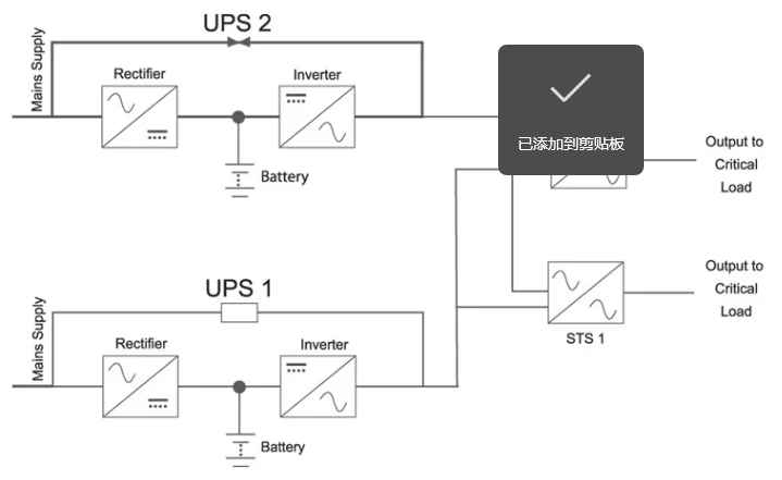
1. Distributed vs. Centralized Bypass N+1 systems use two bypass architectures:
Distributed Bypass: Each UPS contains its own static switch. This design eliminates single points of failure but requires complex coordination. Cost is lower for smaller systems.
Centralized Bypass: A single external static transfer switch serves all UPS units. This simplifies control logic and maintenance. It suits large installations above 500 kVA.
2. Battery Configuration Options Three battery architectures exist for N+1 systems:
| Configuration | Description | Advantages | Disadvantages |
|---|---|---|---|
| Individual | One battery per UPS | Complete isolation, easier maintenance | Higher cost, more space |
| Common Bus | Shared battery system | Lower cost, simpler monitoring | Single point of failure risk |
| Distributed | Battery strings distributed across units | Balance of cost and redundancy | Moderate complexity |
3. Redundancy Levels Comparison Understanding different redundancy levels helps selection:
- N: No redundancy, lowest cost, highest risk
- N+1: One spare unit, cost-effective for most critical applications
- N+2: Two spare units, used when maintenance duration is long
- 2N: Full duplication, maximum reliability, 50% maximum utilization
- 2(N+1): Two fully redundant systems, ultra-critical applications only
Ⅴ. Implementation Best Practices
1. Electrical Design Requirements Implementing N+1 heavy duty UPS systems requires careful planning:
- Separate electrical feeds for each UPS unit
- Independent circuit breakers and protection devices
- Adequate spacing for airflow and maintenance access
- Cable sizing for 125% of rated current minimum
- Grounding systems meeting IEEE standards
2. Synchronization and Load Balancing Successful parallel operation depends on:
- Voltage regulation within ±1% across all units
- Frequency synchronization within 0.1 Hz
- Phase angle difference less than 1 degree
- Current sharing imbalance below 5%
- Active load control via CAN bus or Ethernet communications
3. Environmental Considerations Heavy duty UPS systems require:
- Operating temperature: 20-25°C optimal
- Relative humidity: 40-60% non-condensing
- Clean air filtration (dust reduces capacitor life)
- Vibration isolation for installations near machinery
- Fire suppression systems suitable for electrical equipment
Ⅵ. Applications and Industry Use Cases
1. Data Center Implementation Modern data centers require N+1 at minimum. Facilities implement:
- Row-based UPS distribution with N+1 per pod
- Centralized UPS halls serving multiple data halls
- Lithium-ion battery systems for reduced footprint
- Integration with DCIM for predictive maintenance
2. Industrial Manufacturing Semiconductor fabs and automotive plants use N+1 heavy duty UPS systems for:
- Process control systems
- Robotic manufacturing lines
- Quality inspection equipment
- Safety instrumented systems
Power quality is critical. Voltage sags can ruin entire production batches worth millions.
3. Healthcare Infrastructure Hospitals deploy N+1 redundancy for:
- Operating theaters
- Imaging departments (MRI, CT scanners)
- Life support systems
- Electronic medical records
Regulatory requirements often mandate N+1 or better for patient care areas.
Ⅶ. Maintenance and Operational Excellence
1. Regular Testing Protocols Verify N+1 functionality quarterly:
- Simulate UPS failure by disabling one unit
- Verify load transfers without interruption
- Check battery autonomy under load
- Test static switches and bypass mechanisms
- Validate alarm notifications and remote monitoring
2. Predictive Maintenance Strategies Modern heavy duty UPS systems offer:
- Remote monitoring via SNMP and Modbus
- Battery impedance testing to predict failure
- Thermal imaging of connections
- Capacitor life modeling based on operating hours
- Fan speed monitoring indicating bearing wear
3. Lifecycle Management Plan for component replacement:
- Batteries: 3-5 years for VRLA, 10-15 years for lithium-ion
- Capacitors: 5-7 years for DC bus, 7-10 years for AC filters
- Fans: 5-6 years depending on operating environment
- Power modules: 15-20 years with proper maintenance
Ⅷ. Future Trends in Redundant UPS Technology
1. Lithium-Ion Battery Adoption Lithium-ion batteries reduce weight by 60% and footprint by 50%. They tolerate higher temperatures and offer 10-year lifespans. N+1 systems benefit from faster recharge times and higher discharge rates.
2. Modular and Scalable Designs Modern systems allow adding UPS capacity in 50 kVA increments. This pay-as-you-grow approach matches infrastructure investment to actual load growth.
3. AI-Driven Predictive Analytics Machine learning algorithms analyze operational data to predict failures weeks in advance. This enables scheduled maintenance before problems impact redundancy.
4. Integration with Renewable Energy N+1 UPS systems increasingly incorporate solar and wind power. Battery storage provides ride-through during renewable intermittency while maintaining critical load protection.
Conclusion N+1 redundant heavy duty UPS systems provide the optimal balance of reliability, cost-efficiency, and operational flexibility for critical power applications. Implementing parallel architecture with intelligent automatic failover logic ensures continuous operation even during component failures. As technology evolves toward lithium-ion batteries, modular scalability, and predictive analytics, N+1 configurations remain the industry standard for organizations that cannot tolerate power interruptions.
Organizations should assess their critical load requirements, maintenance capabilities, and uptime targets when designing N+1 systems. Working with experienced power system engineers ensures proper implementation of parallel architecture, synchronization, and fault-tolerant switching logic.
References
- International Electrotechnical Commission (IEC)Official website: www.iec.ch
- Underwriters Laboratories (UL)Official website: www.ul.com
- European Committee for Standardization (CEN)Official website: www.cen.eu
- Standardization Administration of China (SAC)Official website: www.sac.gov.cn
- Zhongguancun Energy Storage Industry Technology Alliance (CNESA)Official website: www.cnESA.org
- International Organization for Standardization (ISO)Official website: www.iso.org