Welcome to BKPOWER!












How to Size an Industrial UPS for Your Facility
TIPS:Properly sizing an industrial UPS power supply requires systematic analysis of equipment loads, redundancy requirements, and future expansion needs. Facility managers must inventory all critical loads, calculate true power requirements including power factor, and select appropriate redundancy configurations from N to 2N. This comprehensive guide explains how to size industrial UPS systems for your facility, covering load calculations, battery runtime sizing, and future-proofing strategies to ensure reliable power protection for years to come.
Ⅰ. Introduction
Power protection failures cost industrial facilities millions annually. Manufacturing downtime, data loss, and equipment damage result from inadequate UPS systems. Yet many organizations size their UPS power supply incorrectly from the start. They either under-size, risking overload failures, or over-size, wasting capital on unused capacity.
Understanding how to size industrial UPS systems requires systematic methodology. You must inventory all critical loads accurately. You must calculate true power requirements including power factor and inrush currents. You must determine appropriate redundancy levels. You must plan for future expansion. Finally, you must size battery backup for required runtime.
This guide provides comprehensive sizing methodology for industrial uninterruptible power supply systems. We cover load calculation techniques, redundancy configuration selection, and future-proofing strategies. Whether protecting a manufacturing line, data center, or critical infrastructure, these principles ensure proper UPS sizing.
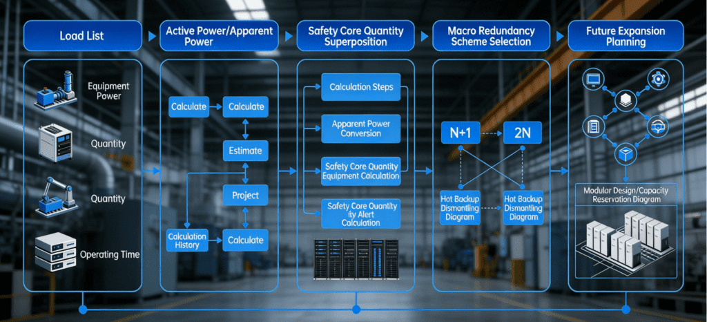
Figure 1: Comprehensive UPS sizing process showing load inventory, calculation steps, redundancy options, and future expansion planning.
Ⅱ. Critical Load Inventory and Classification
1. Identifying Essential Equipment
UPS sizing begins with thorough equipment inventory. Not every device requires UPS protection. You must distinguish critical loads from non-essential equipment.
Critical loads requiring UPS protection:
- Servers, storage, and network equipment (IT infrastructure)
- Industrial control systems (PLCs, DCS, SCADA)
- Safety systems (emergency shutdown, fire detection)
- Communication systems (telephone, radio, monitoring)
- Essential lighting and emergency systems
- Medical equipment (life support, patient monitoring)
Non-critical loads (normal power acceptable):
- General lighting and HVAC
- Office equipment (printers, copiers)
- Non-essential production equipment
- Kitchen and break room appliances
- Convenience outlets
Document every critical load with specifications. Record nameplate ratings for voltage, current, and power. Note equipment type and function. Identify which loads must operate simultaneously versus sequentially.
2. Understanding Load Characteristics
Different equipment types present different loading characteristics. Accurate sizing requires understanding these differences.
Resistive loads convert electricity directly to heat. Examples include heaters and incandescent lighting. These present unity power factor (1.0) and no inrush current. Calculation is straightforward: Power (W) = Voltage (V) × Current (A).
Inductive loads include motors and transformers. These present lagging power factor (typically 0.7-0.9) and high inrush currents (5-8× running current). Motors starting across-the-line create severe transient loads. Variable frequency drives (VFDs) reduce inrush but add harmonic distortion.
Electronic loads include computers and IT equipment. These present non-linear current draw with crest factors up to 3:1. Power factor correction (PFC) power supplies improve to 0.95-0.99, but harmonic content remains.
Mixed industrial loads combine all types. Manufacturing facilities typically see 0.8-0.9 power factor with significant harmonic distortion. Sizing must account for worst-case combinations.
3. Creating the Load Inventory Spreadsheet
Systematic documentation prevents sizing errors. Create a comprehensive inventory with these columns:
- Equipment ID and description
- Quantity of identical units
- Nameplate voltage (V)
- Nameplate current (A)
- Nameplate power (W or kW)
- Estimated power factor
- Simultaneity factor (% time running simultaneously)
- Inrush multiplier (for motor loads)
- Criticality rating (essential vs. important)
Sum the running load first. Then calculate maximum demand considering simultaneity. Finally, verify inrush capacity for motor starting sequences.
Example Load Inventory:
| Equipment | Qty | kW Each | PF | Simultaneity | Total kW |
|---|---|---|---|---|---|
| Servers | 20 | 0.5 | 0.95 | 100% | 10.0 |
| Network gear | 10 | 0.2 | 0.90 | 100% | 2.0 |
| PLC rack | 1 | 2.0 | 0.85 | 100% | 2.0 |
| VFD – Motor | 3 | 5.0 | 0.88 | 80% | 12.0 |
| Emergency lights | 50 | 0.02 | 1.0 | 100% | 1.0 |
| TOTAL | 27.0 kW |
Ⅲ. Power Calculation Methodologies
1. Converting kW to kVA
UPS ratings express in kVA (apparent power). Load calculations typically produce kW (real power). Conversion requires power factor:
kVA = kW ÷ Power Factor
Continuing the example above:
- Total kW: 27.0 kW
- Weighted average PF: (10×0.95 + 2×0.90 + 2×0.85 + 12×0.88 + 1×1.0) ÷ 27 = 0.91
- Required kVA: 27.0 ÷ 0.91 = 29.7 kVA
However, this calculation assumes ideal conditions. Real-world sizing requires additional factors.
2. Applying Diversity and Growth Factors
Not all loads operate at full capacity simultaneously. Diversity factors account for this reality:
Diversity Factor = Sum of Individual Maximum Demands ÷ Maximum Coincident Demand
Typical diversity factors:
- Data centers: 0.8-1.0 (high simultaneity)
- Manufacturing: 0.6-0.8 (staggered operations)
- Mixed facilities: 0.7-0.9
Apply a 20-30% growth factor for future expansion. This prevents immediate obsolescence when adding equipment.
Revised Calculation:
- Base kVA: 29.7 kVA
- Diversity factor (0.8): 29.7 × 0.8 = 23.8 kVA
- Growth factor (1.25): 23.8 × 1.25 = 29.75 kVA
- Adjusted requirement: 30 kVA minimum
3. Inrush and Surge Considerations
Motor starting and transformer energization create temporary overloads. UPS systems must handle these without transferring to bypass.
Motor Starting Current: Typically 6-8× running current for across-the-line starters. VFDs reduce this to 1.5-2×. Size UPS for either:
- 150% overload for 60 seconds (standard industrial UPS), or
- 125% overload for 10 minutes (extended overload models)
Transformer Inrush: Energizing transformers creates 8-12× current spikes for 1-3 cycles. UPS inverter current limiting must accommodate this without shutdown.
Crest Factor: Non-linear loads draw peak currents higher than RMS values. IT equipment crest factors reach 3:1. UPS must deliver peak currents without voltage distortion.
Unless motor loads are substantial (>30% of total), standard UPS overload capacity typically suffices. For motor-heavy applications, specify extended overload capability or add external motor starting provisions.
Ⅳ. Redundancy Configuration Selection
1. Understanding N, N+1, and 2N Configurations
Redundancy determines system availability. Higher redundancy increases cost but reduces failure risk.
N Configuration (No Redundancy):
- Single UPS supports entire load
- UPS failure = power loss to all protected equipment
- Lowest cost, lowest availability (99.9% typical)
- Suitable for non-critical applications where brief outages acceptable
N+1 Configuration (Parallel Redundancy):
- N UPS modules carry the load, +1 provides backup capacity
- Any single module can fail without interruption
- Higher availability (99.99% typical)
- Cost premium: 25-40% above N configuration
- Most common for critical industrial applications
2N Configuration (System-plus-System):
- Two completely independent UPS systems
- Each can support 100% of load independently
- Ultimate reliability (99.999% achievable)
- Cost premium: 80-100% above N configuration
- Used for life safety, financial trading, nuclear applications
2. Selecting Appropriate Redundancy
Redundancy selection balances risk tolerance against budget constraints.
N Configuration Acceptable When:
- Downtime costs are manageable (<$10,000/hour)
- Loads can tolerate brief transfer to bypass
- Maintenance can be scheduled during planned outages
- Generator backup exists for extended outages
N+1 Configuration Recommended When:
- Downtime costs significant ($10,000-100,000/hour)
- 24/7 operation required without interruption
- Multiple UPS modules desirable for load scalability
- Maintenance must occur during normal operations
2N Configuration Required When:
- Downtime costs extreme (>$100,000/hour or life safety)
- Zero single points of failure mandated
- Concurrent maintenance essential
- Regulatory compliance demands highest reliability
Example Sizing with Redundancy:
- Calculated load: 30 kVA
- N configuration: 30 kVA UPS selected
- N+1 configuration: 2 × 20 kVA UPS modules (40 kVA total, any one supports 30 kVA)
- 2N configuration: 2 × 30 kVA UPS systems (60 kVA total, each independent)
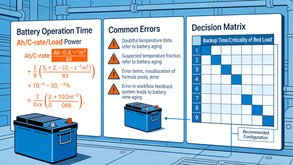
Figure 2: Battery runtime calculations, common sizing mistakes, and decision matrix for load criticality versus backup time requirements.
Ⅴ. Battery Sizing and Runtime Calculation
1. Determining Required Backup Time
UPS battery backup duration depends on application needs and alternative power sources.
Short Duration (5-15 minutes):
- Generator backup available
- Goal: Bridge to generator start and stabilization
- Typical: Data centers with generators, manufacturing with standby power
- Smaller, more economical battery systems
Medium Duration (15-60 minutes):
- No generator backup, or extended transfer time
- Goal: Controlled shutdown or wait for utility restoration
- Typical: Critical process completion, small facilities
- Standard battery configurations
Long Duration (1-8 hours):
- Remote locations without generators
- Goal: Extended operation during prolonged outages
- Typical: Telecommunications, oil and gas, emergency services
- Large battery banks or alternative energy storage
Select runtime based on maximum expected outage duration. Factor in worst-case scenarios: severe storms, grid failures, generator maintenance windows.
2. Battery Capacity Calculation
Battery sizing follows the formula:
Runtime (minutes) = (Battery Ah × System V × Efficiency × Discharge Factor) ÷ (Load kW × 1000) × 60
Where:
- Battery Ah: Ampere-hour rating at 20-hour rate
- System V: DC bus voltage (typically 192V or 384V for industrial UPS)
- Efficiency: UPS inverter efficiency (typically 0.90-0.95)
- Discharge Factor: Battery capacity multiplier (0.7 for 30-min discharge, 0.5 for 60-min)
- Load kW: Protected load in kilowatts
Example Calculation:
- Required runtime: 30 minutes
- Load: 27 kW
- System voltage: 384V
- Efficiency: 0.93
- Discharge factor (30-min): 0.7
Rearranging for Battery Ah: Ah = (Runtime × Load × 1000) ÷ (System V × Efficiency × Discharge Factor × 60) Ah = (30 × 27 × 1000) ÷ (384 × 0.93 × 0.7 × 60) Ah = 810,000 ÷ 15,000 = 54 Ah minimum
Select next standard size: 60 Ah or 100 Ah for margin.
3. Battery Technology Selection
Three main battery technologies serve UPS applications:
Valve-Regulated Lead-Acid (VRLA):
- Standard choice for most applications
- 3-5 year typical lifespan
- Moderate cost, established reliability
- Temperature sensitive (reduce 50% life per 10°C rise)
- Maintenance-free operation
Lithium-Ion (Li-Ion):
- Emerging technology gaining market share
- 10-15 year lifespan
- Higher initial cost, lower lifecycle cost
- Compact, lightweight (50% smaller than VRLA)
- Sophisticated battery management required
- Higher fire risk (requires safety systems)
Nickel-Cadmium (Ni-Cd):
- Extreme temperature tolerance (-40°C to +50°C)
- 15-20 year lifespan
- High cost, declining availability
- Toxic materials (environmental concerns)
- Used only for specialized harsh environments
For standard industrial applications, VRLA remains cost-effective. Consider Li-Ion for space-constrained installations or long-term cost optimization.
Ⅵ. Future-Proofing and Expansion Planning
1. Scalability Considerations
Facility power requirements grow over time. UPS systems should accommodate expansion without complete replacement.
Modular UPS Architecture:
- Add capacity by inserting additional power modules
- “Pay-as-you-grow” approach
- N+1 redundancy maintained as capacity expands
- Ideal for data centers and growing manufacturing
Oversizing Strategy:
- Size UPS at 125-150% of current calculated load
- Provides immediate headroom for minor additions
- Cost-effective for predictable, modest growth
- Risk: Operating at low load reduces efficiency
Parallel System Expansion:
- Add parallel UPS systems as load grows
- Maintains redundancy across expansion
- Requires space and electrical infrastructure planning
- Best for large, phased facility expansions
2. Physical Space Planning
UPS systems occupy significant floor space. Plan for:
- UPS cabinet footprint (growth capacity)
- Battery bank space (separate room often required)
- Maintenance clearance (front, rear, side access)
- Heat dissipation and cooling requirements
- Cable routing and electrical infrastructure
Battery rooms require special consideration:
- Ventilation for hydrogen gas (VRLA batteries)
- Temperature control (25°C optimal)
- Spill containment (for flooded batteries)
- Security and access restrictions
- Fire detection and suppression
3. Electrical Infrastructure Coordination
UPS integration affects facility electrical systems. Coordinate with:
- Switchgear and circuit breaker sizing
- Generator capacity (UPS load plus battery charging)
- Transformer sizing (kVA rating must include UPS)
- Distribution panel layouts
- Grounding and neutral management
Generator sizing particularly important. UPS loads present non-linear characteristics that challenge generator voltage regulation. Size generators 125-150% of UPS rated input kVA for stable operation.
Ⅶ. Common Sizing Mistakes and How to Avoid Them
1. Undersizing Errors
Undersizing leads to overload failures and premature equipment damage.
Mistake: Ignoring power factor UPS rated in kVA, loads calculated in kW. Failing to convert creates 10-20% undersizing.
Solution: Always calculate kVA requirement: kVA = kW ÷ PF
Mistake: Neglecting inrush currents Motor starting currents exceed UPS overload capacity.
Solution: Identify all motor loads. Specify extended overload UPS (150% for 60s) or add motor starting provisions.
Mistake: Disregarding future growth Immediate needs only, no expansion capacity.
Solution: Apply minimum 20% growth factor. Consider modular designs for unpredictable growth.
2. Oversizing Errors
Oversizing wastes capital and reduces operational efficiency.
Mistake: Oversizing for unspecified “safety margin” Doubling calculated load “just to be safe.”
Solution: Use systematic calculation with standardized factors. Excess beyond 25-30% growth factor wastes money.
Mistake: Specifying 2N redundancy for unjustified applications Ultimate reliability when N+1 suffices.
Solution: Quantify downtime costs. Select redundancy matching financial risk, not fear.
Mistake: Excessive battery runtime Specifying 4-hour backup when 30 minutes suffices.
Solution: Analyze actual outage scenarios. Size batteries for realistic requirements.
Ⅷ. Conclusion
Properly sizing an industrial UPS power supply requires systematic analysis, not guesswork. Following the methodology in this guide ensures reliable, cost-effective power protection.
Begin with thorough load inventory. Calculate true power requirements including power factor and diversity. Select redundancy appropriate to application criticality. Size batteries for realistic runtime needs. Plan for future expansion without over-specifying.
The time invested in proper sizing pays dividends through years of reliable operation. Correctly sized UPS systems protect critical loads efficiently. They avoid costly failures from undersizing. They prevent capital waste from oversizing. They scale gracefully as facility needs evolve.
Document your sizing calculations. Maintain load inventories as equipment changes. Review UPS capacity annually. This proactive management ensures your UPS power supply continues meeting facility needs throughout its operational life.
References
- International Electrotechnical Commission (IEC)Official website: www.iec.ch
- Underwriters Laboratories (UL)Official website: www.ul.com
- European Committee for Standardization (CEN)Official website: www.cen.eu
- Standardization Administration of China (SAC)Official website: www.sac.gov.cn
- Zhongguancun Energy Storage Industry Technology Alliance (CNESA)Official website: www.cnESA.org
- International Organization for Standardization (ISO)Official website: www.iso.org