Welcome to BKPOWER!












What Does Uninterruptible Power Supply Do?
TIPS:An uninterruptible power supply protects critical loads from outages and electrical disturbances. A UPS system uses stored energy, power electronics, and control functions to maintain load continuity. An uninterruptible power supply can also improve power quality, depending on topology and configuration. A UPS system may support safe shutdown, generator ride-through, voltage regulation, and critical infrastructure reliability.

Ⅰ. What Does a UPS Do?
1. Direct Answer
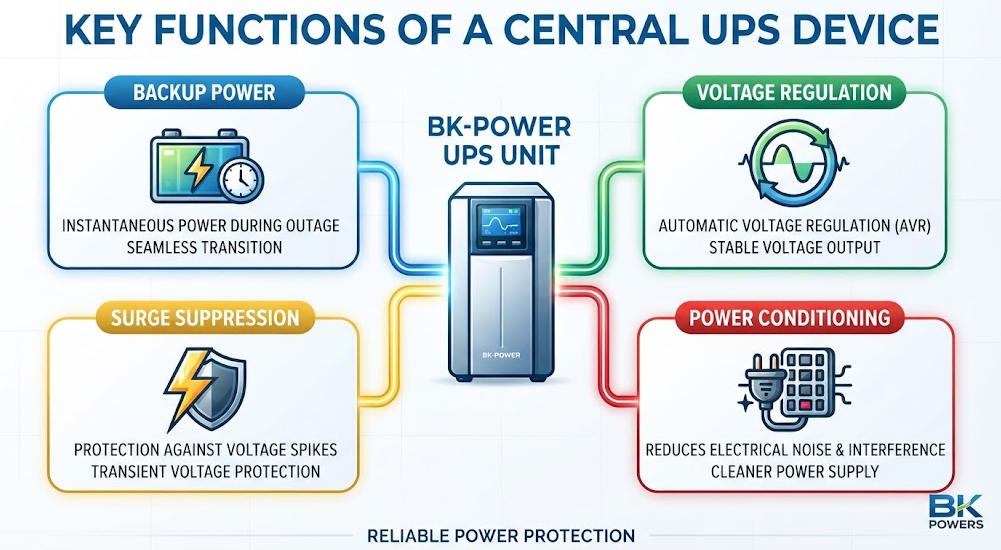
A UPS keeps critical electrical equipment powered when the normal utility supply is interrupted or becomes unacceptable.
Its primary functions include:
- Providing backup energy during a power outage.
- Maintaining power continuity for critical loads.
- Supporting controlled shutdown when an outage continues.
- Regulating voltage in UPS designs that provide voltage regulation.
- Improving certain power-quality characteristics.
- Bridging utility failure and generator startup.
- Monitoring input, output, load, battery, and alarm conditions.
- Supporting redundant critical-power architectures.
NIST defines a UPS as a system that provides an alternative power source after the primary source is lost, while IEEE describes UPS systems as power-protection infrastructure for applications such as data centers, hospitals, industrial controls, and telecommunications.
2. What a UPS Does Not Do
A UPS is not a universal solution for every electrical problem.
It does not automatically provide unlimited backup time. It does not replace a generator for long-duration outages. It does not replace grounding, bonding, circuit protection, or a properly coordinated surge-protection system.
The actual protection depends on the UPS topology and configuration.
For example, an online double-conversion UPS supplies the load through its inverter during normal operation. A standby UPS normally supplies the load through the utility path and transfers to its inverter when required.
Therefore, statements such as “all UPS systems provide zero transfer time” or “all UPS systems provide the same power conditioning” are technically incomplete.
Ⅱ. How Does a UPS Work?
1. Basic Electrical Architecture
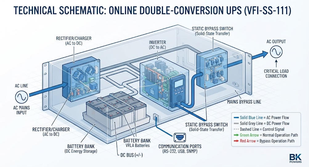
A simplified UPS architecture can be represented as:
AC Input → Rectifier/Charger → DC Bus → Inverter → AC Load
An energy-storage system connects to the DC side.
The exact architecture depends on the UPS topology.
IEEE identifies the rectifier, energy storage, inverter, and static bypass as fundamental elements of many UPS architectures.
The purpose of the architecture is to separate the critical load from at least some of the disturbances that can occur on the normal electrical supply.
2. Rectifier
The rectifier converts AC input power into DC power.
In an online double-conversion UPS, the rectifier normally supplies the DC bus during normal operation.
The DC bus then supplies the inverter.
The rectifier can also charge the battery through the UPS charging system.
Modern UPS rectifiers may use power-factor-correction techniques to improve input current characteristics. The actual input performance depends on the UPS design.
3. DC Bus
The DC bus is the electrical link between the input conversion stage, energy-storage system, and inverter.
During normal operation, energy flows from the utility through the rectifier to the DC bus and then to the inverter.
During an outage, stored battery energy supports the DC bus.
This allows the inverter to continue generating AC output for the critical load.
4. Battery
The battery stores electrical energy for use during an interruption.
Common UPS battery technologies include:
- VRLA lead-acid.
- Flooded lead-acid.
- Lithium-ion.
- Other application-specific storage technologies.
Battery selection depends on more than nominal capacity.
Engineers should consider:
- Required autonomy.
- Discharge characteristics.
- Ambient temperature.
- Charging method.
- Battery management.
- Installation conditions.
- Maintenance requirements.
- Expected service life.
- Replacement strategy.
- Safety requirements.
Lithium-ion batteries can offer advantages in energy density, footprint, lifecycle, and charging characteristics, but VRLA remains relevant for many UPS applications. Eaton notes that both technologies continue to serve different application requirements.
5. Inverter
The inverter converts DC power into AC power.
For an online double-conversion UPS, the inverter is the normal source of power for the critical load.
Its performance affects:
- Output voltage.
- Output frequency.
- Waveform quality.
- Harmonic distortion.
- Dynamic response.
- Load compatibility.
A high-quality inverter is especially important for sensitive electronic and industrial loads.
However, the phrase “pure sine wave” alone does not fully describe inverter performance. Engineers should also evaluate output regulation, THD, dynamic response, overload capability, and compatibility with the connected load.
6. Static Bypass
A static bypass provides an alternative power path around the main UPS conversion system.
It can be used during certain:
- Overload conditions.
- UPS faults.
- Maintenance operations.
- Abnormal operating conditions.
The bypass is important for availability, but it should not be confused with battery backup.
When the load is on bypass, the electrical characteristics depend on the bypass source and facility distribution system.
Ⅲ. What Happens When Utility Power Fails?
1. Normal Operation
During normal operation, the UPS monitors the incoming electrical supply.
Depending on topology, the utility may directly supply the load or supply the UPS conversion system.
At the same time, the battery remains available for an interruption.
The control system may monitor:
- Input voltage.
- Output voltage.
- Frequency.
- Load level.
- Battery voltage.
- Battery state.
- Operating mode.
- Temperature.
- Fault conditions.
2. Power Disturbance
When the input voltage or frequency moves outside the UPS operating window, the UPS control system determines the appropriate response.
The response depends on the topology.
A standby UPS normally transfers the load to the inverter.
A line-interactive UPS may use voltage regulation before relying on the battery.
An online double-conversion UPS already supplies the load through its inverter during normal operation.
This is why the phrase “transfer time” must be used in context.
Eaton identifies transfer time as the time required for a UPS to move a load to battery power, while online architectures fundamentally differ because the inverter already carries the load during normal operation.
3. Battery Operation
During an outage, the battery provides DC energy.
The inverter converts that energy into AC power.
The available runtime depends on:
- Actual load power.
- Battery capacity.
- Battery voltage.
- UPS efficiency.
- Battery condition.
- Temperature.
- Discharge characteristics.
- End-of-discharge voltage.
- Battery aging.
Therefore, battery Ah capacity alone cannot provide a reliable runtime prediction.
4. Utility Restoration
When acceptable utility power returns, the UPS returns to the appropriate normal operating mode.
The battery charger then replenishes the energy used during the outage.
Repeated outages can create an important operational issue.
If the battery has insufficient recharge time between outages, the second event may occur with reduced available battery capacity.
Ⅳ. What Power Problems Can a UPS Protect Against?
1. Power Outages
The most important function is maintaining load continuity during a utility interruption.
Without backup power, a sudden outage can cause:
- Server shutdown.
- Network interruption.
- PLC resets.
- Data corruption.
- Production interruption.
- Communication failure.
- Loss of unsaved work.
A UPS provides stored energy so that critical equipment can continue operating or shut down in a controlled manner.
Eaton identifies power continuity and system shutdown as central UPS functions.
2. Voltage Sags
A voltage sag is a temporary reduction in voltage.
Depending on load characteristics, sag magnitude, and duration, a sensitive load may malfunction or shut down.
A line-interactive UPS may correct certain voltage variations through automatic voltage regulation.
An online double-conversion UPS can provide tighter output control because the load is supplied through the inverter.
3. Overvoltage
Overvoltage can increase electrical stress on connected equipment.
A UPS with appropriate voltage-regulation and protection functions can reduce the effect of some abnormal voltage conditions.
However, the exact protection range must be taken from the UPS specification.
4. Surges and Transients
Surges and transients may result from:
- Utility switching.
- Large load switching.
- Fault conditions.
- Lightning-related events.
- Internal electrical disturbances.
UPS equipment may include surge-protection and filtering functions.
However, a UPS should not be treated as a complete lightning-protection system.
A properly designed installation may require coordinated SPD protection, grounding, bonding, and upstream protection.
5. Frequency Variations
Frequency-sensitive equipment can be affected when the supply moves outside its permitted range.
An online UPS can regulate output frequency through its inverter, depending on the operating mode and design.
This capability distinguishes UPS technology from equipment designed only to regulate voltage.
6. Electrical Noise
Some UPS systems can attenuate certain forms of electrical noise.
Potential sources include:
- Switching power supplies.
- Motors.
- Variable-frequency drives.
- Industrial equipment.
- Electromagnetic interference.
The level of filtering depends on the topology and filtering system.
Therefore, engineers should avoid claiming that every UPS eliminates all electrical noise.
Ⅴ. UPS Topologies Explained
1. Why UPS Topology Matters
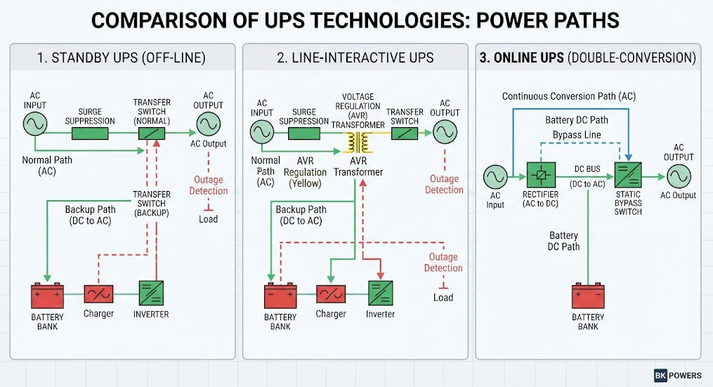
UPS topology determines the normal power path and the response to disturbances.
The three commonly discussed architectures are:
- Standby or offline UPS.
- Line-interactive UPS.
- Online double-conversion UPS.
DOE materials also distinguish UPS architectures using voltage-dependence classifications such as VFD, VI, and VFI.
2. Standby or Offline UPS
A standby UPS normally supplies the load through the utility path.
The inverter remains available until a power disturbance requires battery operation.
During an outage, the system transfers the load to the inverter.
This architecture is commonly used where cost and basic outage protection are more important than maximum power conditioning.
Typical applications include:
- Desktop computers.
- Home-office equipment.
- Small network devices.
- Non-critical electronic loads.
3. Line-Interactive UPS
A line-interactive UPS normally maintains a utility-based power path while providing voltage-regulation functions.
Automatic voltage regulation can correct certain input-voltage conditions without continuously using battery energy.
This makes line-interactive systems useful where voltage fluctuations occur but the application does not require the full architecture of an online UPS.
Typical applications include:
- Network equipment.
- Small server rooms.
- Office IT systems.
- Telecom equipment.
- Selected industrial controls.
4. Online Double-Conversion UPS
An online UPS uses a double-conversion architecture:
AC → DC → AC
The rectifier converts AC input to DC.
The inverter then converts DC into controlled AC output.
The critical load normally receives power from the inverter.
As a result, when utility power fails, the load does not need a conventional utility-to-inverter transfer.
This architecture is widely considered for critical applications such as:
- Data centers.
- Industrial control.
- Medical infrastructure.
- Telecommunications.
- Process automation.
- Critical IT systems.
5. UPS Topology Comparison
| Characteristic | Standby / Offline | Line-Interactive | Online Double-Conversion |
|---|---|---|---|
| Normal load path | Utility | Utility with regulation | Inverter |
| Main power conversion | Limited | Partial | Continuous |
| Voltage regulation | Limited/design-dependent | Typically available | Through inverter |
| Battery use during normal operation | Normally not supplying load | Normally not supplying load | Battery integrated with DC architecture |
| Utility failure response | Transfer to inverter | Transfer to inverter | Inverter continues supplying load |
| Power conditioning | Basic | Moderate | Generally stronger |
| Typical application | PC and basic electronics | IT and networking | Critical IT and industrial loads |
| Relative complexity | Lower | Medium | Higher |
This comparison is conceptual.
The actual performance must be verified against the manufacturer’s technical documentation and applicable standards.
Ⅵ. UPS vs Generator: Why They Work Together
1. Different Functions
A UPS and generator solve different power problems.
The UPS provides fast ride-through.
The generator provides long-duration energy.
A generator normally requires time to start and stabilize.
The UPS bridges this interval.
This architecture is particularly important for facilities that cannot tolerate an interruption but do not need to operate entirely from batteries for the duration of a long outage.
2. Typical Architecture
A critical facility may use:
Utility → UPS → Critical Load
with a generator providing an alternative upstream source:
Utility / Generator → UPS → Critical Load
A typical sequence is:
- Utility power fails.
- UPS detects the abnormal condition.
- Battery energy supports the critical load.
- Generator starts.
- Generator reaches acceptable operating conditions.
- Facility power distribution transfers according to its design.
- UPS continues protecting the load.
The exact sequence depends on the facility’s ATS, generator, UPS, and distribution architecture.
3. UPS Runtime Is Not the Same as Generator Runtime
UPS batteries are often designed around the required ride-through period rather than the total duration of a long utility outage.
Eaton’s UPS guidance notes that many standard systems provide short-duration internal battery support, while additional battery modules can extend runtime when required.
The engineering question should therefore be:
How much ride-through time does the facility require?
rather than:
How many hours should the battery last?
Ⅶ. How Do You Size a UPS?
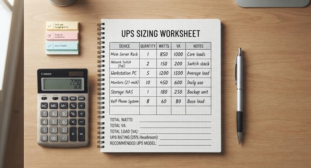
1. Start With the Load
The first step is to identify every load that must remain protected.
Record:
- Voltage.
- Phase.
- Current.
- kW.
- kVA.
- Power factor.
- Inrush current.
- Harmonic characteristics.
- Operating profile.
2. Understand kW and kVA
UPS systems are commonly rated in VA or kVA.
The relationship between apparent power and real power is:
kW = kVA × Power Factor
For example:
A 100 kVA load operating at a power factor of 0.9 has:
100 × 0.9 = 90 kW
However, this calculation alone does not determine the correct UPS rating.
The engineer must also consider:
- UPS power-factor capability.
- Overload rating.
- Transient loads.
- Future expansion.
- Redundancy.
- Operating temperature.
- Battery configuration.
3. Avoid Oversizing
A very large UPS is not automatically a better UPS.
Oversizing can result in:
- Low load utilization.
- Higher capital cost.
- Less efficient operation.
- More unused capacity.
DOE specifically notes that UPS efficiency varies with loading and that lightly loaded systems can waste a significant portion of input energy. DOE also recommends considering modular UPS architectures where systems operate below design conditions or where future growth is expected.
4. Allow for Future Growth
A growing data center or factory may have a significantly larger future load than its current load.
Engineers can consider:
- Modular UPS.
- Parallel UPS systems.
- N+1 redundancy.
- Expandable battery systems.
- Additional power modules.
A modular architecture can allow capacity to grow with the load.
Ⅷ. How Do You Calculate UPS Runtime?
1. Basic Battery Energy
A simplified theoretical calculation is:
Battery Energy ≈ Battery Voltage × Battery Capacity
For example, a nominal 240 V, 100 Ah battery bank has:
240 × 100 = 24,000 Wh
or approximately:
24 kWh of nominal stored energy
However, this does not mean 24 kWh is available at the AC load.
2. Practical Runtime
A simplified estimate is:
Runtime ≈ Usable Battery Energy × UPS Efficiency ÷ Load Power
The result is only an engineering approximation.
Actual runtime is affected by:
- Battery discharge rate.
- Battery temperature.
- Battery age.
- Battery chemistry.
- UPS efficiency.
- DC cutoff voltage.
- Load characteristics.
- Battery configuration.
Therefore, manufacturer runtime curves should be used for final design.
3. Example
Assume:
- Nominal battery energy: 24 kWh.
- Estimated usable fraction: 80%.
- UPS conversion efficiency: 90%.
- Load: 10 kW.
A simplified estimate becomes:
24 × 0.80 × 0.90 ÷ 10 = 1.728 hours
This is not a guaranteed runtime.
The actual result can differ because battery capacity is not a fixed energy reservoir under every discharge condition.
The example demonstrates the calculation method rather than providing a universal performance value.
Ⅸ. UPS Efficiency and Energy Consumption
1. Efficiency Depends on Operating Conditions
UPS efficiency varies with operating conditions.
Important factors include:
- Load percentage.
- Operating mode.
- Input conditions.
- Power factor.
- Converter design.
- Cooling requirements.
DOE explicitly states that UPS efficiency varies with loading and that systems operating lightly loaded can lose a substantial portion of input energy in UPS losses.
2. Why Partial-Load Operation Matters
Consider a facility that installs substantially more UPS capacity than it currently needs.
The UPS may operate at a low percentage of its rated output for years.
Depending on the UPS design, this can reduce efficiency.
Therefore, UPS selection requires a balance between:
- Current load.
- Future growth.
- Efficiency.
- Redundancy.
- Capital cost.
- Maintenance strategy.
3. Modular UPS
Modular UPS systems can address this challenge.
Capacity can be deployed in modules instead of installing the entire future capacity on day one.
This approach can improve capacity utilization and simplify expansion.
DOE specifically identifies modular UPS as an option for applications with future growth or sustained operation below design capacity.
Ⅹ. UPS vs Voltage Stabilizer
1. Fundamental Difference
A UPS primarily provides power continuity and stored-energy backup.
A voltage stabilizer primarily provides voltage regulation.
A voltage stabilizer normally cannot provide battery-backed power during a blackout.
A UPS may provide voltage regulation, but the capability depends on its topology.
2. Engineering Comparison
| Function | UPS | Voltage Stabilizer |
|---|---|---|
| Backup during blackout | Yes | No |
| Battery storage | Typically | No |
| Voltage regulation | Depending on topology | Primary function |
| Frequency regulation | Available in suitable UPS designs | Generally not the primary function |
| Power continuity | Primary function | Not primary function |
| Generator ride-through | Yes, when correctly designed | No |
| Long-duration energy supply | Requires additional storage or source | No |
| Main application | Critical power continuity | Voltage stabilization |
The distinction is important in industrial facilities.
A site with severe voltage fluctuation but reliable utility continuity may need voltage regulation.
A site with frequent outages may need a UPS.
A site with both problems may need coordinated power-protection equipment.
BKPOWER already maintains separate technical content covering UPS and voltage-stabilizer differences.
Ⅺ. Where Are UPS Systems Used?

1. Data Centers
Data centers use UPS systems to protect critical IT and infrastructure loads.
Typical protected equipment includes:
- Servers.
- Storage.
- Network switches.
- Security systems.
- Control systems.
- Critical monitoring equipment.
A UPS can also bridge the interval between utility failure and generator availability.
For high-availability facilities, UPS systems may form part of N+1 or other redundant power architectures.
2. Industrial Automation
Industrial automation can be sensitive to short power disturbances.
Typical loads include:
- PLCs.
- SCADA systems.
- Industrial PCs.
- Sensors.
- Control networks.
- Instrumentation.
- Process-control systems.
Depending on load characteristics, a short interruption can cause a controller reset or process interruption.
The economic impact may be much greater than the energy cost of the outage itself.
3. Healthcare
Healthcare facilities contain electrical loads with different levels of criticality.
UPS systems may support selected:
- Medical electronics.
- IT systems.
- Monitoring equipment.
- Communication systems.
- Control equipment.
The actual UPS design must comply with the electrical and safety requirements applicable to the installation.
UL Solutions identifies healthcare, data centers, server rooms, telecommunications, and financial institutions among UPS application areas.
4. Telecommunications
Telecommunication systems depend on high availability.
UPS systems can protect:
- Network equipment.
- Communication equipment.
- Data transmission systems.
- Control systems.
Battery autonomy and remote monitoring are particularly important for distributed facilities.
5. Finance and Enterprise IT
Financial institutions and enterprise IT systems can be highly sensitive to power interruption.
A UPS can support:
- Servers.
- Network infrastructure.
- Storage.
- Communication systems.
- Transaction systems.
The required architecture depends on the criticality of the application.
Ⅻ. How to Choose the Right UPS
1. Define the Critical Load
Do not start by choosing a UPS model.
Start by identifying the equipment that actually needs protection.
Classify loads into:
- Critical.
- Important.
- Non-critical.
This can prevent unnecessary UPS capacity.
2. Determine Electrical Requirements
Collect:
- Input voltage.
- Output voltage.
- Phase configuration.
- Frequency.
- kW.
- kVA.
- Power factor.
- Inrush current.
- Harmonic characteristics.
3. Select the Topology
| Application | Initial Topology to Evaluate | Main Reason |
|---|---|---|
| Desktop computer | Standby | Basic outage protection |
| Office network | Line-interactive | Backup plus voltage regulation |
| Small server room | Line-interactive or online | Depends on criticality |
| Industrial control | Online | Stronger power continuity and conditioning |
| Data center | Online | Critical load protection |
| Mission-critical facility | Online + redundancy | Availability requirements |
| Variable/growing load | Modular online UPS | Capacity scalability |
| Long utility outages | UPS + generator | Short-term ride-through plus long-duration energy |
This is a starting framework.
The final selection must consider the actual electrical and operational requirements.
4. Determine Runtime
Determine whether the UPS is intended to:
- Support controlled shutdown.
- Bridge generator startup.
- Maintain a process for a defined interval.
- Provide extended backup.
Runtime should be calculated from the load and verified against manufacturer data.
5. Evaluate Redundancy
For critical facilities, consider:
- N.
- N+1.
- 2N.
- Distributed redundant architectures.
The correct architecture depends on the facility’s availability requirements.
6. Review Applicable Standards
IEC 62040-1 addresses UPS safety requirements.
IEC 62040-3 addresses UPS performance and testing.
The current IEC 62040-1 consolidated publication applies to UPS systems with energy storage within the specified scope and establishes safety requirements.
For North American applications, UL 1778 provides a key framework for UPS safety evaluation and certification. UL Solutions describes UL 1778 as the Standard for Uninterruptible Power Systems.
The actual compliance requirements depend on the target market, installation, product construction, and project specifications.
ⅩⅢ. Common UPS Selection Mistakes
1. Choosing Only by kVA
kVA is important, but it is not the entire selection process.
Engineers should also evaluate:
- kW.
- Power factor.
- Inrush.
- Load profile.
- Overload capability.
- Future growth.
- Redundancy.
2. Assuming All UPS Systems Have Zero Transfer Time
This is one of the most common technical misunderstandings.
A standby or line-interactive UPS normally needs a transfer between power paths during certain disturbances.
An online double-conversion UPS normally supplies the load through its inverter.
Therefore, the architecture determines the meaning and importance of transfer time.
3. Assuming a UPS Replaces a Generator
A UPS is normally designed for short-duration ride-through unless an extended battery system is specifically engineered.
A generator can provide much longer energy availability.
For critical infrastructure, the two technologies are often complementary.
4. Ignoring Battery Conditions
A battery’s nominal rating does not guarantee the same usable energy under every condition.
Temperature, age, discharge rate, and battery configuration matter.
5. Oversizing the UPS
Oversizing can increase capital cost and may reduce operating efficiency at low loads.
DOE specifically recommends considering loading and modular architectures when evaluating UPS energy performance.
6. Treating the UPS as the Entire Protection System
A UPS should normally be considered one layer of a broader power architecture.
Other layers may include:
- Surge protection.
- Grounding.
- Bonding.
- Circuit protection.
- Generator systems.
- Distribution redundancy.
- Monitoring.
- Environmental control.
- Battery protection.
ⅩⅣ. What Makes a UPS System Reliable?
1. Correct Electrical Architecture
Reliability starts with system design.
Important considerations include:
- Appropriate topology.
- Correct capacity.
- Battery configuration.
- Bypass architecture.
- Protection coordination.
- Distribution design.
2. Thermal Management
UPS power electronics generate heat.
Thermal conditions can affect component lifetime and battery performance.
The UPS room therefore needs an appropriate environmental design.
3. Battery Management
Battery management should include:
- Monitoring.
- Correct charging.
- Temperature management.
- Periodic inspection.
- Appropriate testing.
- Planned replacement.
4. Monitoring and Communication
Modern UPS systems may provide:
- Input voltage.
- Output voltage.
- Frequency.
- Load percentage.
- Battery condition.
- Alarm status.
- Estimated runtime.
Network connectivity can allow facility operators to monitor the system remotely.
5. Maintenance
A UPS should not be treated as maintenance-free infrastructure.
Depending on system design, maintenance may include:
- Battery inspection.
- Capacitor inspection.
- Cooling-system inspection.
- Connection checks.
- Alarm testing.
- Firmware or monitoring-system maintenance.
- Preventive service.
ⅩⅤ. BKPOWER UPS Solutions
BKPOWER’s current UPS portfolio includes industrial-frequency UPS, high-frequency UPS, rack-mounted UPS, modular UPS, line-interactive UPS, UPS batteries, and battery cabinets. Its modular range includes three-phase online double-conversion systems across multiple capacity configurations.
BKPOWER also publishes technical material covering UPS topology, runtime, UPS power factor, industrial UPS selection, and the relationship between UPS and voltage stabilization.
For an engineering project, the selection process should focus on:
- Actual load.
- kW and kVA.
- Power factor.
- Single-phase or three-phase architecture.
- Required autonomy.
- Utility quality.
- Load sensitivity.
- Redundancy.
- Environmental conditions.
- Battery technology.
- Future expansion.
- Applicable standards.
For industrial applications, online UPS and industrial-frequency UPS architectures can be evaluated according to load characteristics, electrical environment, and required availability.
ⅩⅥ. Final Engineering Takeaway
So, what does a UPS do?
The short answer is:
A UPS maintains power continuity for critical loads when the normal electrical supply fails or becomes unacceptable.
The engineering answer is more comprehensive.
A UPS combines:
- Power conversion.
- Energy storage.
- Inverter technology.
- Control systems.
- Switching.
- Protection.
- Monitoring.
Its performance depends on topology, load, battery configuration, operating mode, and system architecture.
For a simple computer, a standby or line-interactive UPS may provide sufficient protection.
For a data center or industrial control system, an online double-conversion UPS may be evaluated because the inverter continuously supplies the load during normal operation.
For a facility with long outages, a UPS may work together with a generator.
For a site with severe voltage instability but limited outage risk, a voltage stabilizer may address a different part of the power problem.
The correct UPS therefore should not be selected from kVA alone.
Engineers should evaluate:
- Load kW.
- Load kVA.
- Power factor.
- Phase configuration.
- Voltage and frequency.
- Inrush characteristics.
- Required runtime.
- Battery technology.
- Efficiency.
- Bypass architecture.
- Redundancy.
- Environmental conditions.
- Applicable safety and performance standards.
IEC 62040-1 establishes UPS safety requirements, while IEC 62040-3 provides requirements for UPS performance and testing.
The most reliable approach is to treat the UPS as part of a critical power protection architecture, not simply as a battery box.
That approach allows engineers to connect power continuity, power quality, battery energy, generator integration, redundancy, efficiency, and lifecycle management into one coherent design.
Collection of Related Information
| Title | Core Content | URL |
|---|---|---|
| UPS System | BKPOWER overall UPS product architecture and product categories | BKPOWER UPS System |
| Modular UPS | Three-phase online double-conversion modular UPS products | BKPOWER Modular UPS |
| High Frequency UPS | High-frequency online UPS and single-phase UPS products | BKPOWER High Frequency UPS |
| UPS Battery | UPS battery products and energy-storage solutions | BKPOWER UPS Battery |
| UPS Topology Comparison | Offline, line-interactive and online UPS comparison | UPS Topology Comparison |
| UPS Backup Time | UPS runtime calculation and battery-runtime optimization | UPS Backup Time Guide |
| Industrial UPS Selection | Industrial UPS sizing, selection and engineering considerations | Industrial UPS Selection Guide |
| UPS Power Factor | kW, kVA, power factor and load-capacity considerations | UPS Power Factor Guide |
| UPS vs Voltage Stabilizer | Technical differences between backup power and voltage regulation | UPS vs Voltage Stabilizer |
| UPS for Computers | Computer backup power, topology and application guidance | UPS for Computers |
Reference Sources
| Title | Core Content | URL |
|---|---|---|
| IEEE Technology Navigator | UPS definition, power continuity, power-quality protection and major UPS components | IEEE — Uninterruptible Power Supplies |
| International Electrotechnical Commission — IEC 62040-1 | UPS safety requirements | IEC 62040-1 |
| International Electrotechnical Commission — IEC 62040-3 | UPS performance and testing requirements | IEC 62040-3 |
| U.S. Department of Energy | UPS efficiency, loading, modular UPS and energy-management guidance | DOE — Purchasing Energy-Efficient UPSs |
| NIST | Technical definition of an uninterruptible power supply | NIST — Uninterruptible Power Supply |
| UL Solutions | UL 1778 UPS safety and certification framework | UL Solutions — UPS Safety and Compliance |
FAQ
Q1.What is the main difference between VA and Watts when sizing a UPS?
Direct Answer: VA (Volt-Amps) represents apparent power, while Watts represent real power. The ratio between them is the Power Factor (PF).
Technical Explanation: The relationship is defined by the formula Watts = VA × PF. UPS systems are rated in both VA and Watts. The load’s power factor determines how much real power (Watts) the UPS can support for a given VA rating. A load with a lower power factor will draw more current (higher VA) for the same amount of real work (Watts).
Practical Application: When sizing a UPS, you must ensure that your total load does not exceed either the VA or the Watt rating of the UPS. It is a best practice to size the UPS so that the total load is only 70-80% of its capacity to allow for future growth and ensure optimal efficiency.
Q2.What is the difference between a simulated sine wave and a pure sine wave output?
Direct Answer: A pure sine wave is a smooth, oscillating waveform identical to utility power, while a simulated sine wave is a stepped approximation.
Technical Explanation: Active Power Factor Corrected (PFC) power supplies, common in modern servers and high-end workstations, require a pure sine wave input to operate correctly. A simulated or stepped sine wave can cause these power supplies to malfunction, overheat, or shut down unexpectedly due to the harmonic distortion in the waveform.
Practical Application: For any critical equipment, especially servers, medical devices, or equipment with an active PFC power supply, an online UPS with a pure sine wave output is mandatory. Standby and some line-interactive models may use a simulated sine wave, making them suitable only for basic electronics.
Q3.How long will a UPS keep my equipment running during a power outage?
Direct Answer: Runtime depends on the UPS battery capacity and the percentage of the load connected to it. There is an inverse relationship between load and runtime.
Technical Explanation: A UPS’s runtime is not a fixed number. It is determined by the size of its battery bank (measured in Amp-hours) and the power draw of the connected equipment. The heavier the load (i.e., the closer to the UPS’s maximum capacity), the shorter the runtime will be. Manufacturers provide runtime charts that show estimated runtimes at various load levels (e.g., 50%, 75%, 100%).
Practical Application: To determine the required runtime, decide on your goal. Is it just enough time for a graceful shutdown (typically 5-10 minutes)? Or do you need to bridge the gap until a generator starts (typically 10-30 minutes)? Use the manufacturer’s runtime charts to select a UPS and battery configuration that meets your specific runtime goal at your calculated load.
Q4.What is a Static Bypass in a UPS, and why is it important?
Direct Answer: A static bypass is an internal, automatic switch that routes utility power directly to the load, circumventing the UPS’s main power conversion components.
Technical Explanation: It serves as a critical fail-safe mechanism. If the UPS experiences an internal fault, an overload, or overheats, the static bypass switch activates in milliseconds to transfer the load to raw utility power. This prevents a total power loss to the connected equipment. It is also used for maintenance, allowing technicians to work on the UPS while the load remains powered.
Practical Application: The static bypass is a fundamental feature for ensuring high availability in critical environments like data centers. It guarantees that a failure of the protection device (the UPS) does not become the cause of a power outage for the protected load.
Q5. When should I consider using Lithium-Ion batteries in my UPS instead of traditional VRLA batteries?
Direct Answer: Lithium-ion batteries are ideal for applications where space is limited, longer lifespan is desired, and a higher upfront cost is acceptable for a lower total cost of ownership.
Technical Explanation: Compared to traditional Valve Regulated Lead-Acid (VRLA) batteries, Lithium-ion batteries have a much higher energy density (more power in a smaller size), a significantly longer operational life (often 2-3 times the number of charge/discharge cycles), and faster recharge times. They are also less sensitive to temperature fluctuations.
Practical Application: For new data center installations or edge computing locations where floor space is at a premium, lithium-ion UPS systems are an excellent choice. Although the initial purchase price is higher, the extended lifespan (10+ years vs. 3-5 years for VRLA) and reduced cooling requirements often result in a lower total cost of ownership over the life of the system.