Welcome to BKPOWER!












Industrial vs High-Frequency UPS: An Engineering Comparison
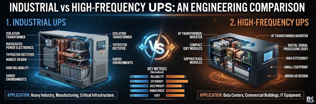
TIPS:Industrial Frequency UPS and High Frequency UPS are both used for critical power protection, but their engineering priorities are different. Industrial Frequency UPS typically emphasizes robust transformer-based architecture and demanding load environments, while High Frequency UPS prioritizes compact design, power density and efficient conversion. Choosing between them requires evaluating load behavior, grid quality, efficiency, installation constraints, redundancy and lifecycle cost rather than comparing price alone.
Ⅰ. Introduction
An uninterruptible power supply (UPS) maintains continuous power to critical loads during grid outages, voltage sags, surges, and harmonic disturbances. Two dominant online double-conversion architectures exist: industrial (line/low) frequency UPS and high frequency UPS. Many facility managers and electrical integrators struggle to decide which topology fits their project. The wrong UPS selection can cause nuisance bypass transfers, equipment damage, excessive energy bills, or unplanned downtime.
The core difference lies in power conversion topology and the presence of a line-frequency isolation transformer. Industrial frequency UPS uses SCR rectifiers and a large 50/60Hz output transformer. High frequency UPS uses IGBT high-speed switching and eliminates the heavy line-frequency transformer. This single design change cascades into major differences in overload capability, galvanic isolation, efficiency, footprint, EMI tolerance, and total cost of ownership.
This guide compares both UPS architectures from an engineering perspective. It covers operating principles, performance benchmarks, load suitability, TCO tradeoffs, and practical selection rules. It targets data center managers, industrial automation engineers, power system integrators, facility managers and electrical equipment distributors.
Ⅱ. Core Topology & Working Principle
1. Industrial Frequency UPS (Transformer-Based UPS)
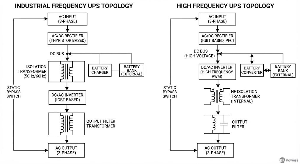
Industrial frequency UPS is also known as line-frequency UPS. Its classic double-conversion power path follows this sequence: AC utility → SCR phase-controlled rectifier → DC bus → inverter → line-frequency isolation transformer → critical load.
The SCR rectifier converts AC input to DC. The inverter converts DC back to AC. The output transformer performs three core functions: voltage transformation, galvanic isolation, and natural current limiting during overload or short-circuit events.
Galvanic isolation breaks the direct electrical connection between input grid and output load. It blocks common-mode noise, ground potential shifts, and transient voltages from propagating to sensitive equipment. The transformer’s magnetic inertia naturally slows the rate of current rise (di/dt). This feature is extremely valuable for inductive industrial loads such as motors, compressors and pumps that generate large inrush currents at startup.
Depending on load characteristics, SCR rectifier designs can have higher input THDi unless paired with a 12-pulse rectifier or active harmonic filter. Traditional 6-pulse SCR rectifiers typically produce higher input harmonic distortion. 12-pulse topologies reduce THDi significantly for heavy industrial sites.
2. High Frequency UPS (Transformerless UPS)
High frequency UPS adopts IGBT high-frequency switching technology, operating at switching frequencies above 20kHz. Its power path is: AC utility → IGBT high frequency rectifier → DC-DC converter → high frequency inverter → critical load. There is no heavy line-frequency isolation transformer in standard models. Some high-frequency systems add a small high-frequency transformer inside DC-DC stage, but this is not equivalent to line-frequency galvanic isolation for heavy fault currents.
High frequency IGBT rectifiers achieve near-unity input power factor and low input THDi without extra harmonic filters. The removal of the large line-frequency transformer cuts weight and footprint drastically. The main limitation comes from IGBT semiconductor vulnerability to large, fast current spikes. IGBTs have tight thermal and current limits. Severe overload or short-circuit events quickly trigger protective bypass transfer.
Ⅲ. Key Technical Parameter Comparison
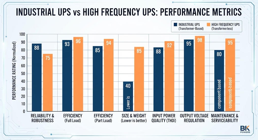
The table below summarizes core technical performance metrics between industrial frequency UPS and high frequency UPS.
| Parameter | Industrial Frequency UPS | High Frequency UPS |
|---|---|---|
| Core Power Device | SCR rectifier + line-frequency transformer | IGBT high frequency rectifier & inverter |
| Galvanic Isolation | Built-in full galvanic isolation via output transformer | No standard galvanic isolation; optional small high-frequency transformer |
| Typical Efficiency | 85%–90% | 92%–96% |
| Overload Rating | 150% for 60 seconds; >300% short-circuit withstand for several cycles | 125% for 60 seconds; limited short-circuit current, fast bypass |
| Input Power Factor | 0.8–0.9 (6-pulse); up to 0.98 (12-pulse) | 0.99 |
| Input THDi | 25–30% (6-pulse); <10% (12-pulse) | <5% |
| Weight (100kVA) | 400–700 kg | 150–250 kg |
| Footprint | Large | Compact |
| EMI / Surge Immunity | Excellent, transformer suppresses transients | Good, depends on electronic filtering |
| Typical Service Life | 10–15 years | 7–10 years |
Table 1: Technical comparison between industrial frequency UPS and high frequency UPS. All values represent typical ranges, actual performance depends on manufacturer design and testing standards.
Ⅳ. Load Type & Application Suitability
1. Industrial Frequency UPS Applications
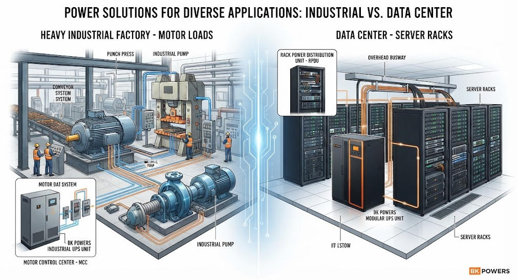
Industrial frequency UPS is preferred for heavy inductive loads and electrically harsh environments. Typical loads include large manufacturing motors, compressors, hydraulic pumps, rolling machines, medical imaging equipment, and power station control systems.
Motor startup generates 5–7 times rated inrush current. The industrial transformer absorbs these current spikes without immediate bypass transfer. Ground potential drift, common-mode noise and frequent grid voltage fluctuations are common in factory environments. Galvanic isolation protects sensitive control systems from ground faults on the load side.
Industrial frequency UPS also fits sites with poor grid quality: frequent voltage sags, surges, harmonics and heavy electromagnetic interference. Mining, oil & gas, rail transit and hospital critical power systems commonly select transformer-based industrial UPS.
2. High Frequency UPS Applications
High frequency UPS is optimized for linear IT loads. Primary deployments include enterprise data centers, server rooms, telecom rooms, office IT infrastructure and cloud computing racks.
IT loads are mostly switching power supplies with low inrush after initial startup. Data center operators prioritize high energy efficiency, compact footprint, scalable modular design and low input harmonics. High frequency modular UPS supports N+X redundancy and hot-swappable power modules. Operators can incrementally add capacity as IT load grows, reducing upfront capital expenditure.
High frequency UPS is less suitable for heavy inductive loads without careful load derating. Repeated motor inrush events may trigger frequent bypass transfers, exposing IT equipment to raw grid power.
Ⅴ. Overload, Short-Circuit and Fault Handling
Overload and short-circuit handling is the most important differentiator for industrial power engineers.
Industrial frequency UPS relies on the transformer’s inherent inductance to limit fault current. During a downstream short circuit, the transformer naturally restricts current rise speed. It can sustain 150% overload for 60 seconds and deliver more than 300% short-circuit current for several AC cycles. This gives downstream circuit breakers enough time to clear the fault without transferring to bypass.
High frequency UPS uses electronic current limiting on IGBT semiconductors. IGBTs cannot survive large sustained fault currents. Most high frequency units only withstand 125% overload for 60 seconds. When fault current exceeds limits, control logic immediately transfers load to static bypass. If the bypass source also contains disturbances, the critical load loses power quality protection.
Depending on load profile, repeated bypass transfers reduce system availability. In data centers, occasional bypass may be acceptable. In continuous manufacturing lines, bypass transfer can stop production and damage expensive tooling.
Ⅵ. Power Quality, Isolation and EMI Performance
Galvanic isolation is often misunderstood. It separates two electrical circuits so no direct conductive path exists between primary and secondary sides. Isolation blocks ground loop currents and common-mode transients.
Industrial frequency UPS has built-in galvanic isolation from the output transformer. This is a passive, robust isolation mechanism. It works even during transient grid events. It isolates load-side ground faults from the UPS input side.
High frequency transformerless UPS does not include this passive isolation. Electronic filters reduce noise, but they cannot provide true galvanic separation. Common-mode noise and ground potential differences can pass through the power conversion circuit. Some high-frequency UPS add optional high-frequency isolation transformers, but these components are not designed to handle large low-frequency fault currents like line-frequency transformers.
EMI immunity is critical in factories with many variable frequency drives and welding equipment. Industrial frequency UPS shows superior performance in high EMI environments. High frequency UPS still meets IEC EMC standards, but noise can penetrate easier under extreme industrial interference.
Ⅶ. Efficiency, Footprint and Total Cost of Ownership
1. Energy Efficiency
High frequency UPS achieves higher conversion efficiency because it eliminates transformer copper and iron losses. Typical efficiency runs from 92% to 96%. In large data centers operating 24/7, a few percentage points of efficiency improvement create large annual electricity savings.
Industrial frequency UPS has higher static losses in the transformer. Typical efficiency ranges from 85% to 90%. For low utilization industrial sites with short annual operating hours, the energy penalty may not dominate TCO. For continuous full-load operation, the power loss accumulates over years.
2. Space and Weight
High frequency UPS removes heavy iron cores and copper windings. It reduces cabinet weight and footprint significantly. Modular high-frequency UPS can stack multiple power modules in one frame. Data centers with limited floor space and low floor loading capacity favor high frequency designs.
Industrial frequency UPS is heavy and large. It requires reinforced floor structure, larger equipment rooms and higher transportation cost. Site construction budget must include civil reinforcement.
3. TCO Breakdown
TCO includes CAPEX, energy cost, battery replacement, maintenance, floor space and downtime risk cost. The table below compares TCO factors.
| TCO Item | Industrial Frequency UPS | High Frequency UPS |
|---|---|---|
| Initial CAPEX per kVA | Higher | Lower |
| Annual Energy Loss | Higher | Lower |
| Floor Space & Civil Works | Higher | Lower |
| Maintenance Complexity | Medium, transformer needs inspection | Medium, semiconductors need thermal check |
| Downtime Risk on Inductive Loads | Lower | Higher |
Table 2: TCO comparison for industrial frequency UPS vs high frequency UPS.
For IT data centers running 24/7 with linear loads, high frequency UPS usually delivers better TCO. For heavy industrial plants with inductive loads and poor grid quality, industrial frequency UPS reduces unplanned downtime risk. Downtime cost often outweighs higher energy and CAPEX costs.
Ⅷ. Maintenance & Reliability Considerations
Industrial frequency UPS uses mature SCR and transformer technology. Transformers have long service life if kept within temperature limits. Capacitors are the main wear components. Transformer windings only require periodic insulation resistance testing. The design has decades of field-proven reliability in heavy industry.
High frequency UPS relies on high-power IGBT modules, high-speed control circuits and DC-DC converters. Semiconductors degrade under thermal cycling. Dust and high ambient temperature accelerate aging. Modular high-frequency UPS simplifies repair via hot-swap modules, but spare module inventory increases maintenance planning.
Ambient operating environment matters. Industrial sites often have dust, humidity, vibration and wide temperature swings. Industrial frequency UPS is more tolerant of these harsh conditions. High frequency UPS requires cleaner, temperature-controlled equipment rooms to maintain rated service life.
Ⅸ. Selection Decision Framework
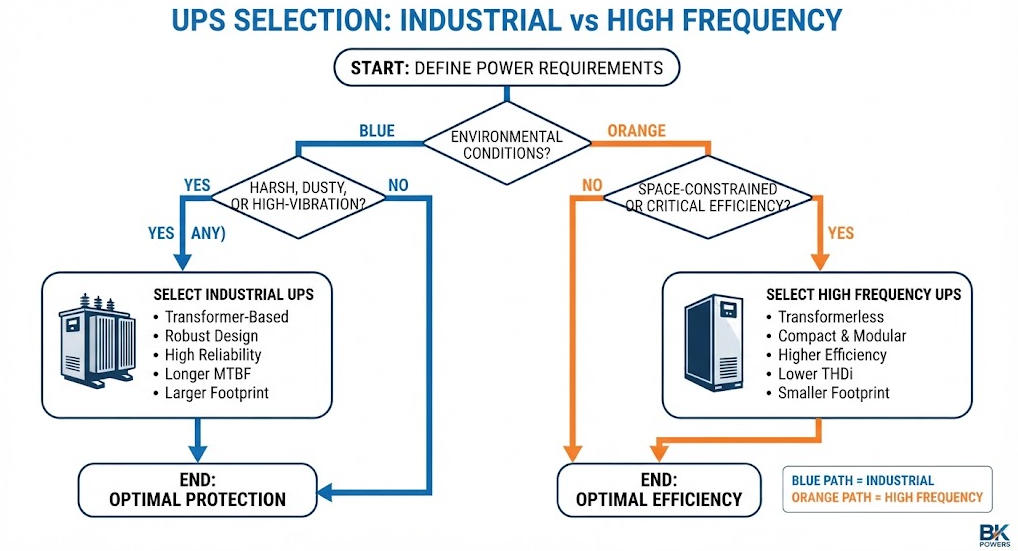
Use this decision checklist to select between industrial frequency UPS and high frequency UPS.
| Selection Question | Choose Industrial Frequency UPS | Choose High Frequency UPS |
|---|---|---|
| Load type | Heavy inductive loads: motors, compressors | Linear IT loads: servers, network switches |
| Grid quality | Poor grid: frequent sags, surges, EMI | Stable utility power |
| Isolation requirement | Need galvanic isolation / ground loop protection | No ground potential drift concerns |
| Overload / inrush current | Large motor inrush, frequent short-circuit risk | Low inrush IT loads |
| Site space constraint | Sufficient room and reinforced floor | Limited floor area, low floor loading |
| Operating hours | Intermittent operation | 24/7 continuous full load |
Table 3: UPS selection decision matrix.
Selection Rules
- If your load includes motors or inductive equipment with high inrush current, prioritize industrial frequency UPS.
- If your site has ground potential difference, medical loads or control systems requiring galvanic isolation, select industrial frequency UPS.
- If you deploy in a Tier III/IV data center with clean IT loads and stable grid, high frequency UPS is the default choice.
- If floor loading is weak or room space is limited, high frequency modular UPS is preferred.
- If the site has continuous heavy EMI and voltage disturbances, industrial frequency UPS offers better robustness.
Ⅹ. Common Misconceptions
1. Misconception: High frequency UPS is always better and newer
High frequency topology is newer, but newer does not equal universally better. Its advantages focus on efficiency, weight and footprint. It sacrifices natural overload and fault current handling. The correct topology depends on load and environment, not release date.
2. Misconception: Industrial UPS means old and unreliable
Transformer-based industrial UPS uses proven power electronics. Many units run reliably for more than 12 years in factories. Reliability metrics remain strong when operated within rated environmental limits.
3. Misconception: Galvanic isolation can be fully replaced by electronic filters
Electronic filters suppress noise. They cannot provide the low-frequency fault current isolation and ground loop blocking offered by a line-frequency transformer. Filtering and galvanic isolation serve different protection purposes.
Ⅺ. Conclusion
Industrial frequency UPS and high frequency UPS are two mature online double-conversion topologies with distinct design priorities. Industrial frequency UPS delivers robust galvanic isolation, strong overload and short-circuit capability for heavy inductive loads and harsh electrical environments. High frequency UPS provides high efficiency, compact footprint, low input harmonics and modular scalability for IT data center loads.
There is no universal “better” UPS topology. The optimal choice comes from analyzing load profile, grid quality, isolation needs, site constraints and total cost of ownership including downtime risk. Electrical engineers and facility managers must evaluate these factors before finalizing UPS procurement and system design.
Related UPS Articles & Resources
| Title | Core Content | URL |
|---|---|---|
| Understanding Industrial Power UPS Specifications Guide | Industrial UPS input voltage, THD, overload capability, crest factor and specification selection | Industrial Power UPS Specifications Guide |
| How to Choose the Right Industrial Uninterruptible Power Supply | UPS load calculation, kVA sizing, power factor and engineering selection | How to Choose the Right Industrial UPS |
| Can Industrial Frequency UPS Handle Motor Startup Surges? | Motor starting current, transient load and industrial UPS selection | Industrial UPS Motor Startup Guide |
| UPS Power Factor & Load Capacity Guide | Power factor, kVA/kW relationship and UPS capacity calculation | UPS Power Factor & Load Capacity Guide |
| UPS Backup Time Calculator | Battery capacity, backup time, load management and runtime optimization | UPS Backup Time Calculator Guide |
| High Frequency UPS Product Portfolio | BKPOWER high-frequency online UPS products, single-phase and three-phase models | High Frequency UPS Products |
| Industrial Frequency UPS | BKPOWER industrial-frequency UPS product category | Industrial Frequency UPS Products |
| BK-L33-40KVA Three-Phase High-Frequency UPS | Transformerless high-frequency online UPS architecture and technical features | BK-L33-40KVA Product Page |
| High Frequency UPS Price Comparison | Commercial comparison of high-frequency UPS purchasing considerations | High Frequency UPS Price Comparison |
Reference Sources
| Title | Core Content | URL |
|---|---|---|
| IEC 62040-1 — Uninterruptible Power Systems: Safety Requirements | UPS safety requirements, energy-storage systems, AC output and installation requirements | IEC 62040-1 |
| IEC 62040-3 — UPS Performance and Test Requirements | UPS performance characteristics, testing and classification methodology | IEC Webstore |
| U.S. Department of Energy — Energy Efficiency | Energy efficiency principles relevant to power systems and electrical equipment | U.S. Department of Energy |
| ENERGY STAR — Uninterruptible Power Supplies | Energy-efficiency considerations and UPS efficiency evaluation | ENERGY STAR |
| IEEE Standards Association | Electrical engineering standards and technical guidance relevant to power quality and power electronics | IEEE Standards Association |
FAQ
Q1: What is the main difference between industrial frequency UPS and high frequency UPS?
A: Industrial frequency UPS uses a built-in line-frequency transformer for galvanic isolation and natural overload handling. High frequency UPS uses IGBT switching without a large output transformer, achieving higher efficiency and smaller size, but with weaker short-circuit withstand. This makes industrial UPS better for heavy inductive loads.
Q2: Can high frequency UPS work for motor loads?
A: High frequency UPS can support motor loads only after strict load derating. Motor startup inrush currents may trigger frequent bypass transfers. If your site has large motors, industrial frequency UPS is normally recommended for stable operation and fault tolerance.
Q3: Does high frequency UPS provide galvanic isolation?
A: Standard transformerless high frequency UPS does not provide galvanic isolation. Optional small high-frequency transformers can be added, but they cannot deliver the same low-frequency fault isolation and ground-loop protection as the line-frequency transformer in industrial UPS.
Q4: Which UPS topology has better energy efficiency?
A: High frequency UPS delivers higher efficiency from 92% to 96% because it eliminates transformer iron and copper losses. Industrial frequency UPS runs at 85–90%. The efficiency gap creates measurable energy savings for data centers operating continuously at high load.
Q5: How to decide between industrial UPS and high frequency UPS for my project?
A: Evaluate load profile, grid quality, isolation needs and site floor capacity. Choose industrial UPS for inductive loads, poor grid or ground isolation requirements. Select high frequency UPS for IT loads, stable grid and projects needing compact footprint and high efficiency.